Steel Building Learn the Basics
Whether you are jumping into the world of steel building for a personal, business, government, or house of worship project, you are probably going to think you are in a different world; a world that doesn’t speak your language!
The steel building industry has its own language, terms, and definitions. Taking time to learn the lingo of steel building allows you to effectively describe your project to metal building companies you speak to and better understand and compare your project quotes.
Building Sides
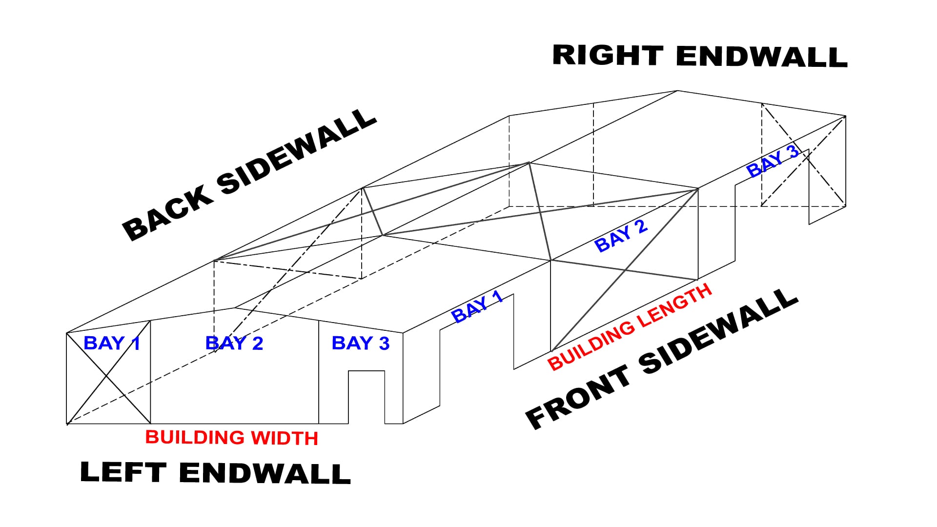
Of course, the very first thing that needs to be noted about steel building is that in the industry, all 4 walls have a very specific name – that never changes. Using a small 40′ x 60′ simple steel building as an example and going clockwise starting at 6 o’clock – the steel building’s 4 walls are properly referred to as:
Front Sidewall: The front wall running the length of the steel building
Left Endwall: The left wall running the width of the steel building
Back Sidewall: The rear wall running the length of the steel building
Right Endwall: The left wall running the width of the steel building
It does not matter where you are standing or what your point of reference is – these names do not change.
When using these terms to describe the walls/sides of a steel building, Buck Steel often abbreviates them as: FSW (front sidewall), LEW (left endwall), BSW (back sidewall), and REW (right endwall).
In addition to referencing the walls as above, each wall is divided into “bays”. A bay is simply the space in between frame lines (on sidewalls) or the space between columns (on endwalls). Bays are always numbered left to right. In the above picture, both sidewalls and both endwalls each have 3 bays.
Framed Openings
The size, quantity, and location of framed openings for roll-up doors, walk doors, and windows can have a significant impact on the cost of the project. All steel building framed openings are not the same.
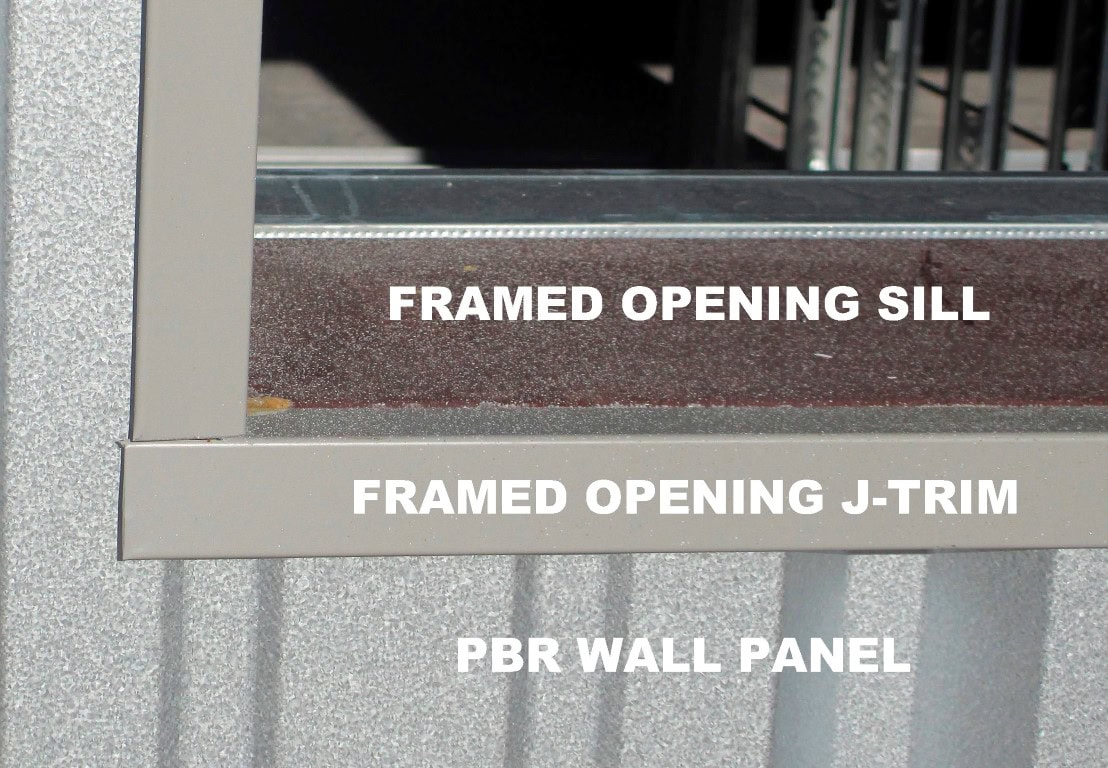
A standard framed opening consists of a header (horizontally across the top of the opening), a sill (horizontally across the bottom of the opening), and jambs (vertical members on the left and right of the opening). In addition, the framed opening will have a piece of j-trim on all 4 sides so that the bare edges of the wall panel are hidden and that the framed opening looks finished.
Because steel building commercial rollup doors are installed on the inside of the steel building they are located “behind” the framed opening. As a result – the header and jambs of the rollup door framed opening are visible and look unfinished.
For this reason all Buck Steel building framed openings for commercial rollup doors come with full cover trim in addition to j-trim. The full cover trim covers the jambs and header of the rollup door framed opening providing a “finished” appearance.
Framed Opening Locations
A steel building needs to have each of its 4 sides braced in order to stiffen the structure. For most small to mid-size steel building projects, bracing one bay on each wall is sufficient. The most inexpensive and common form of steel building bracing is by using diagonal cables in the form of an “x” – often referred to as “cable bracing” or “x-bracing”.
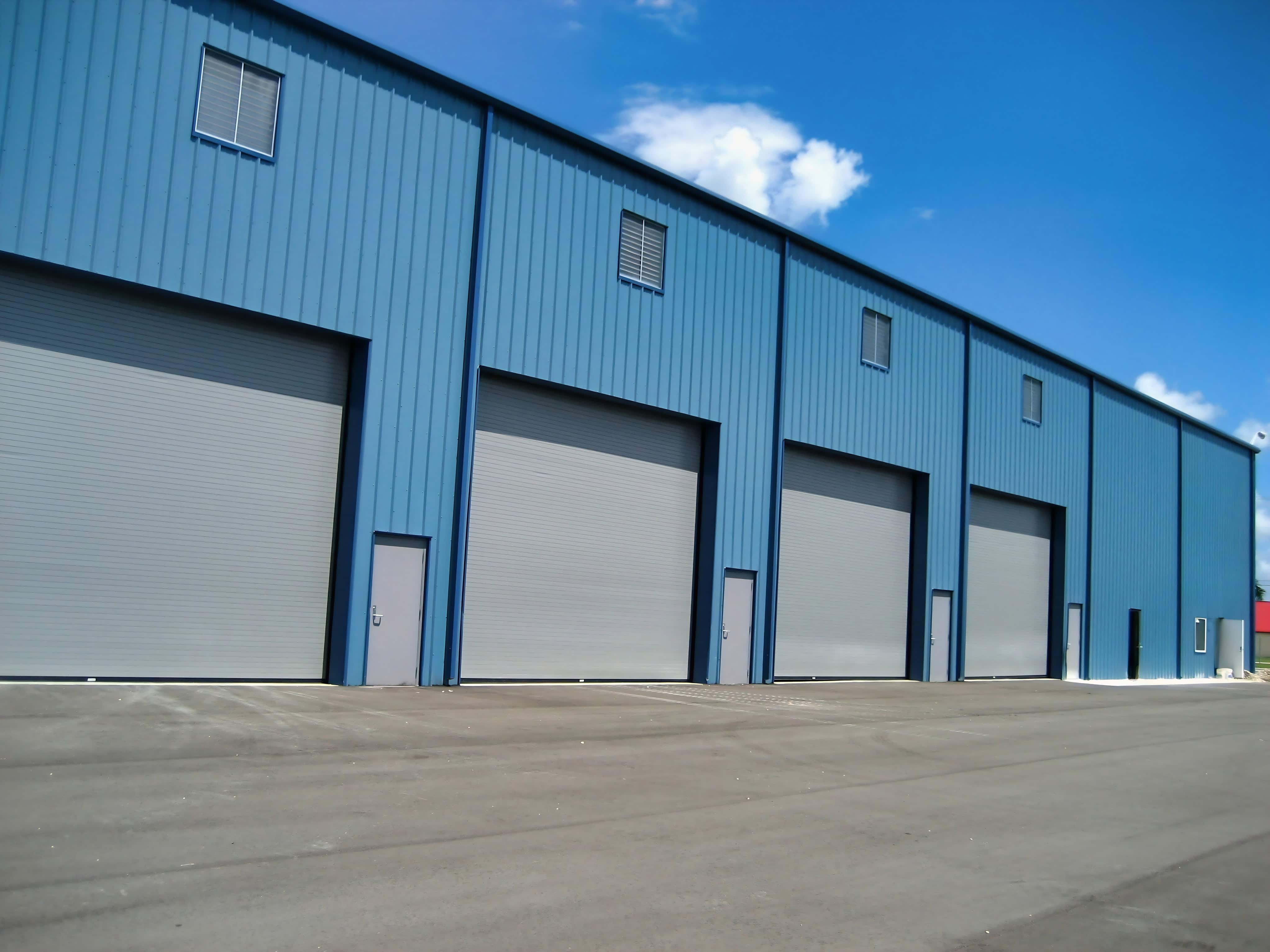
With this in mind and using the image of the building at the top of this page as a guide – you can see that the placement of the one rollup door framed openings in Bay 1 and the other rollup door framed opening in Bay 3 allowed Bay 2 to be used for cable bracing. If the customer would have requested 3 roll-up doors on the front of their steel building – then it would have been impossible to use cable bracing in Bay 2 and a more costly form of wind framing (a portal frame) would have had to have been used.
The point of this is that placement of framed openings in a steel building affect the ability of the steel building engineer to brace the building – and can ultimately affect the cost of the steel building. If during conversations about your steel building project, the designer is not asking you for details about location of framed openings – be very suspicious.
Building Drawings
While discussing steel building and the process of completing a project, you will no doubt come across the use of the word “plans” and/or “drawings” several times. Those not dealing with steel building every day can easily get confused when discussing anchor bolt plans, approval drawings, permit drawings, final drawings, and foundation drawings.
Approval Drawings
Steel building drawings that are NOT stamped by a licensed engineer but rather are a preliminary set of building drawings that are subject to correction and/or modification by the client or their architect. These kinds of drawings are most often seen on projects involving more complex steel building projects where one or more architects is involved.
Permit Drawings
these steel building drawings that ARE stamped by a licensed engineer and are the drawings that will be submitted to the local building department when applying for a permit.
Final Drawings
sometimes also referred to as erecting drawings are drawings that are NOT stamped and are used for on-site assembling of the pre-fabricated steel building. Final drawings show in greater detail (and identify) the connections and components to allow for proper erecting of the building and might also reflect minor changes made after the permit drawings for the steel building were produced and stamped by the Engineer.
Foundation Drawings
Foundation Drawings
Are the engineering for the foundation on which your steel building will sit. They are stamped by a licensed engineer and will be submitted to the local building department when applying for a permit. Buck Steel refers to these as “Stamped Engineered Foundation Drawings“. If you are required to obtain a permit for your project – you will be required to produce a set of foundation drawings stamped by a licensed engineer.
Anchor Bolt Drawings
Are drawings that specify the exact placement of anchor bolts in the concrete slab for your steel building. Buck Steel refers to these as “Anchor Bolt Plans”. The anchor bolt drawings and the Foundation Drawings serve as a set of very detailed instructions for the concrete contractor so that the concrete pad is ready to accept the steel building when erecting starts.
Generally speaking, it is highly likely that the steel building you are getting quotes on will INCLUDE a set of building drawings and a set of anchor bolt plans. When comparing quotes though, be sure that they all clearly specify in writing that both are included.
Many steel building companies and steel building brokers will likely NOT provide or even quote you on the needed foundation drawings – leaving it up to you to find a local engineer to provide you with them. Buck Steel is proud to be able to quote you on foundation design for your steel building as we have an in-house engineer who’s only job is to design concrete slabs for steel building projects!
The Buck Steel Advantage
Whether you are considering a 40′ x 60′ metal garage, a 10,000 sq. ft. steel warehouse, a 3,000 sq. ft. steel airplane hangar, a 30,000 sq. ft. open steel riding arena, or a new steel church for your congregation, a steel building project can sometimes be intimidating to navigate alone. Whether for personal or business use, you want to minimize the cost of your steel building project while maximizing the benefit it provides.
Why not give yourself The Buck Steel Advantage and have a reputable metal building supplier, serving the steel building customer for nearly 20 years, with 1,000’s of completed projects, guide you through the metal building process?
Getting started is easy with Buck Steel
Request A Quote Today or Call (866) 574-2825 to speak to a member of our team.


We welcome your comments and questions!